Optical Cathodoluminescence Microscope Stage
Optical Microscope
Fiber Optic Grating
Spectrometer
(EDX) Energy-Dispersive
X-ray Spectroscopy
System
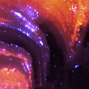
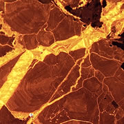
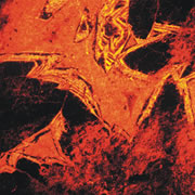
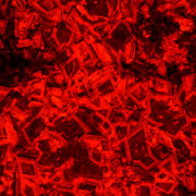
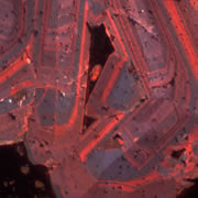
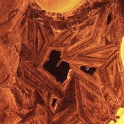
Image Gallery
Scientific Papers
What is Cathodoluminescence?
Cathodoluminescence (CL) is the emission of photons of characteristic wavelengths from a material that is under high-energy electron bombardment. The electron beam is typically produced in an electron microprobe (EPMA) or in a cathodoluminescence microscopy attachment to a petrographic microscope (Optical-CL) or scanning electron microscope (SEM-CL). The nature of CL in a material is a complex function of composition, lattice structure and superimposed strain or damage on the structure of the material. Different minerals exhibit fluorescent or phosphorescent kinetic behaviour which can have an effect on the quality of the CL images, depending on the manner in which the image is obtained.
What is Optical-CL (Optical-Cathodoluminescence)
Optical cathodoluminescence (optical-CL) permits optical examination or imaging of a sample through the attachment of an evacuated CL-stage to an optical microscope. The CL-stage attachment uses a cathode gun to bombard a sample with a beam of high-energy electrons. The resulting luminescence in minerals allows us to see textures and compositional variations that are not otherwise evident using light microscopy. The stage allows X-Y movement of the sample to examine much of the surface area in the sample.
What is Cold-cathode CL
Cold-cathode CL microscopes are the simplest and most economic type most commonly used. A cold-cathode CL is an attachment to a microscope that allows the sample to be examined optically with the microscope and with CL in the same area. In a cold-cathode CL system the electron beam is generated by the discharge that takes place between the cathode at negative high voltage and anode at ground potential in ionised gas at a moderate vacuum of ~10-2 Torr. The result is relatively low-intensity CL in most CL-active silicate minerals. The CL response in the sample can be viewed through the objective lens of the microscope or the image can be recorded with high-speed film or with a digital camera. Unlike other electron bombardment techniques like electron microscopy, cold cathodoluminescence microscopy provides positive ions along with the electrons which neutralise surface charge buildup and eliminate the need for conductive coatings to be applied to the specimens.
Cathodoluminescence Microscopy Applications
In geology, mineralogy and materials science and semiconductor engineering, a scanning electron microscope with specialised optical detectors, or an optical cathodoluminescence microscope, may be used to examine internal structures of semiconductors, rocks, ceramics, glass, etc. in order to get information on the composition, growth and quality of the material.
CL emissions can provide general information on the trace elements contained in minerals or the production of mechanically induced defects in the crystals. Perhaps more importantly for the geologic context, the distribution of the CL in a material gives fundamental insights into such processes as crystal growth, replacement, deformation and provenance. These applications include:
- Investigations of cementation and diagenesis processes in sedimentary rocks
- Provenance of clastic material in sedimentary and metasedimentary rocks
- Details of internal structures of fossils
- Growth/dissolution features in igneous and metamorphic minerals
- Deformation mechanisms in metamorphic rocks.
Cathodoluminescence Theory
Solid-state band theory provides a way to explain the luminescence phenomenon. An insulating solid material (such as quartz or calcite) can be visualised as having a valence band and a conduction band with an intervening band gap (forbidden gap).
If a crystal is bombarded by electrons with sufficient energy, electrons from the lower-energy valence band are promoted to the higher-energy conduction band. When the energetic electrons attempt to return to the ground state valence band, they may be temporarily trapped (on the scale of microseconds) by intrinsic (structural defects) and/or extrinsic (impurities) traps. If the energy lost when the electrons vacate the traps is emitted is in the appropriate energy/wavelength range, luminescence will result. Most of the photons fall in the visible portion of the electromagnetic spectrum (wavelengths of 400-700 nm) with some falling in the ultraviolet (UV) and infrared (IR) portions of the electromagnetic spectrum.
There are several possible ways in which the traps can interact to produce luminescence. Once the electrons are excited to the conduction band they may not encounter a trap and fall to the valence band or they move randomly through the crystal structure until a trap is encountered. From that trap, the electron might return to the ground state or it may encounter multiple traps emitting photons with wavelengths dependent on the energy differences. The intensity of the CL is generally a function of the density of the traps.
In a flat sample that is > 10 µm, the resolution of a CL image will be inherently reduced because of the significantly larger depth/volume in which the CL is being excited.
Intrinsic luminescence is characteristic of the host lattice. It can be due to non-stoichiometry (vacancies), structural imperfections (poor ordering in the crystal, radiation damage, shock damage, etc.) and impurities (non-activators that distort the lattice).
Extrinsic luminescence results from impurities in the structure. The impurities generate luminescent centres and are most commonly transition elements, rare earth elements and actinide elements (due to the occurrence of valence electrons in either "d" or "f" orbitals, see below). These impurities are generally the most common source of CL in minerals. There are several categories of interactions that influence the character of the CL.
Activators – these are trace elements (substitutional) that promote CL in a material. In general, CL intensity will increase with concentration to a point. With further increase in concentration, the CL will decrease (i.e. self-quench) dependent on the structure of the lattice. Examples of important activators in minerals include Mn2+, Cr3+, Fe3+, Ti4+ and rare earth elements (REEs). A further consideration is that the intensity and wavelength of the CL is dependent on the electron configuration of the activator ion and the nature of the lattice that holds the ion. In some minerals the CL is dependent primarily on the type of REE because the CL commonly involves shielded 4f and 5f orbitals and does not have much influence from bonds with nearby atoms. For activators such as the first-row transition elements the 3d electronic levels are sensitive to the site geometry. For the example of Mn2+ in various carbonate minerals, the influence of the local bonding environment and site geometry has a significant effect on the CL response.
Sensitisers (co-activators) – these are ions that must coexist with another activator, absorb energy, re-emit it to an activator and enhance the CL response of the activator. For example, Pb2+ can serve as a sensitiser for Mn2+ located in calcite.
Quenchers – there are ions that inhibit or eliminate CL in a material. The most important quencher in minerals is typically Fe2+, but Co2+, Ni2+ and Fe3+ are also known to act as quenchers.
CL Spectra – Numerous activators may be present in a mineral, and can generate a complex spectrum in the visible light region. CL instruments equipped with a monochrometer (or spectrophotometer) can resolve the CL signal for multiple peaks. By placing a focused electron beam on an area of interest such as a highly luminescent zone in a mineral, it is possible to determine the wavelength(s) that contribute to areas of anomolous luminescence; these wavelengths are commonly interpreted as being derived from a specific element in a given valence state. Conversely, the monochrometer can be tuned to a single or limited range of wavelengths, and you can then obtain a map of all areas that have the same luminescence; this can then be interpreted as a map of the distribution of a given activator element. Because the CL signal is sensitive to the chemical state of polyvalent elements (e.g. Mn+2 v. Mn+3), it is possible to do chemical mapping (in addition to compositional mapping) of redox reactions by showing the distribution of relatively oxidised or reduced domains in a sample.
SOURCES: Darrell Henry, Louisiana State University http://serc.carleton.edu/research_education/geochemsheets/CLTheory.html